Home Installation
For individual homes, the installation is even simpler:
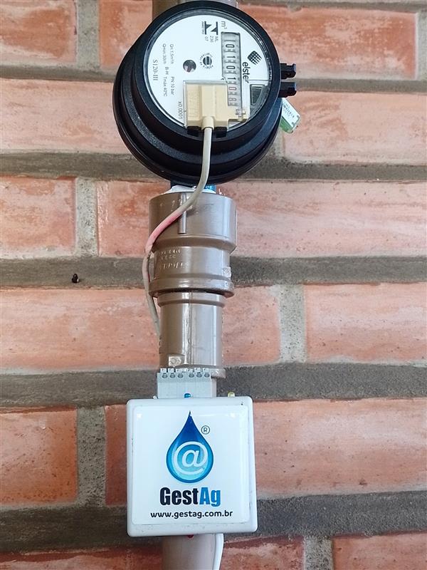
- Connects directly to the main water meter
- Monitors total home consumption
- Detects leaks and waste
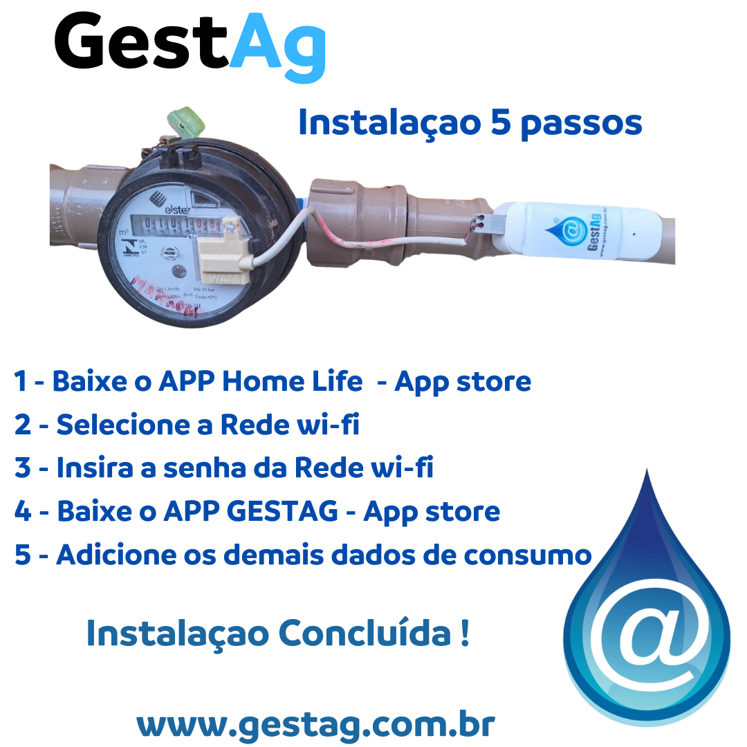
Installing GESTAG is simple and can be carried out by specialized technicians. The process involves:
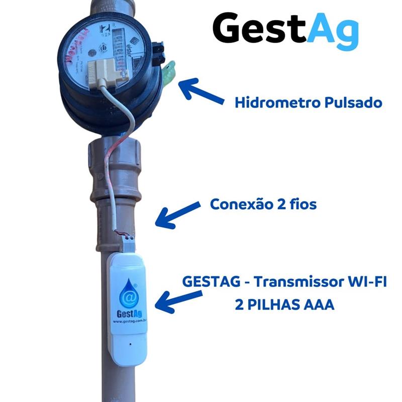

Water meters with pulse output are required to connect with GESTAG.
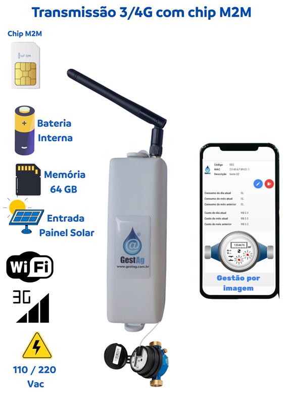
The location must have 3G network coverage for data transmission.
An electrical power outlet must be near the installation points.
For condominiums, GESTAG can be installed in different ways:

Series Connection

Installation by Floors
Steps, advantages, and support — with real images of the equipment.
For individual homes, the installation is even simpler:
Key practical benefits for everyday use:
Our technical team offers:
Objective: to guarantee a reliable backhaul between the GestAg modules on each floor and the concentrator (core router or switch) using fiber optics — maintaining continuous telemetry, low latency, and a securely isolated IoT network.
How it works: each GestAg (RJ45 port) is connected to an RJ45<->SFP media converter on the floor; the fiber goes up/down to the core switch with SFP/SFP+ bays.
How it works: on each floor, an L2 switch with RJ45 ports and 1-2 SFPs is installed. The GestAg units connect via copper, and the switch uplink goes via fiber to the core.
How it works: an OLT in the MDF feeds optical splitters in the shaft; on each floor there is an ONU that provides RJ45 for local GestAg units.
| Criterion | Converter | L2 Switch | PON |
|---|---|---|---|
| Initial cost | low | medium | high (OLT) / low per ONU |
| Scalability | medium | high | very high |
| Manageability | low | high | medium/high |
| Floor power dependency | yes | yes | yes |
| Required ducts | 1 fiber per floor | 1 fiber per floor (or ring) | 1 trunk + splitters |
Examples of minimum sets for each architecture:
Always record initial optical levels to track potential future degradations (bends, dirty connectors, or breaks).
Use this space for a video demonstrating the fiber pulling, ODF termination, connection to the GestAg on each floor, and examples of installations in real buildings.
Intelligent water monitoring with 3G/M2M communication and web dashboards, organized into a clear deployment flow - from the diagnosis phase to project consolidation.